

Each HC6 heater controller can operate up to six heaters and monitor up to 16 thermocouple temperatures. The heaters can be powered manually, by selecting a power level from 0 to 100%, or they can be managed by a PID control, custom-tuned for specific devices. Thermocouple types T and K are supported.
In general, select the controller and channels based on wiring convenience, and "load balancing." Balancing the loads means trying to distribute higher power devices evenly among all of the controllers, rather than concentrating them on one or two controllers. Power is measured in Watts. VTCs are low-power devices, less than 10 W each. High power devices such as large ceramic furnaces might consume as much as 300-400 W. Avoid putting more than 360 W total on any one controller.
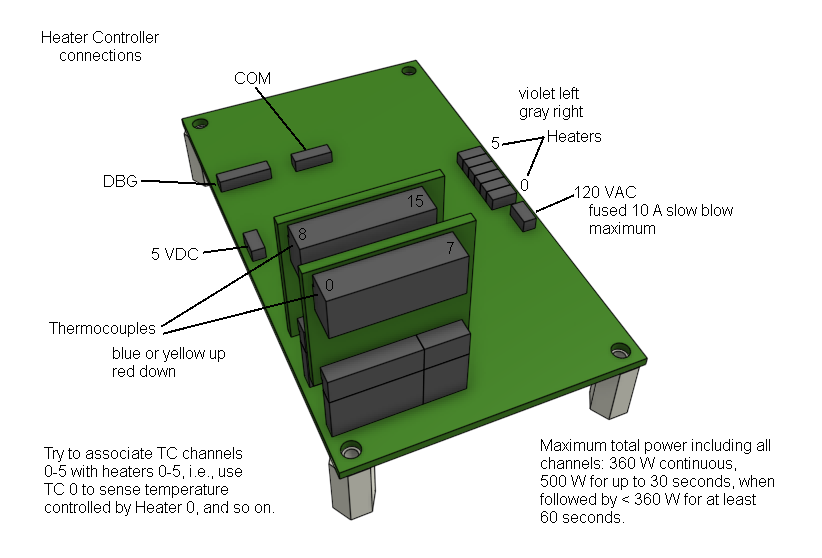
Another convention is sometimes adopted, but is not really important. That convention is to put a heater's temperature sensor on the same-numbered thermocouple channel. For example, if a device is connected to heater channel 3, try to put its temperature-sensing thermocouple on thermocouple channel 3. This is not important, though. Any heater can be configured to use any thermocouple channel as its temperature sensor. By default, the controller firmware assigns the first six thermocouple channels to the heaters in order. However, in a HACS application, the host computer software overrides the default firmware settings and explicitly assigns every heater's thermocouple channel according to the settings file. The only value in maintaining the convention is that, when manually operating the heater controller using a Serial Port Terminal instead of a HACS application, a few configuration commands are saved.
In addition to the VTCs, all of the other heaters on the line should be spliced to violet+gray cables, which then should be routed to a heater controller. For splices, the 1/4" quick-disconnect terminals may be the most convenient. Other options are available, too, such as any of various styles of butt splices. Practically any reliable, insulated electrical connection that is suited to the wire diameters and the temperatures they will be exposed to should be fine. Do not let the violet+gray cables come into contact with anything that will get hot. The ribbon cable insulation must always be kept below 80 °C. (Keep this in mind especially with ceramic fiber furnaces and heat tape.)
Also install whatever thermocouples are needed to monitor temperatures at various devices or locations and route the thermocouple cables to a heater controller.
Never bundle (zip-tie) thermocouple cables together with AC power cables (such as heater cables), and avoid routing the two types of cables directly alongside each other. Where this is impossible, keep the gap between the two cable types as wide as possible, and the length of their adjacency as short as possible.
Do not cut thermocouple cables too short, and avoid splicing or extending them. If an extension is unavoidable, it must be made from the appropriate "thermocouple extension wire," as it is called by the vendors who sell it. The metal in thermocouple extension wire is essentially the same composition as the original thermocouple wires. Be sure not to reverse the metals when connecting the extension wire: connect the red-insulated or red-striped wires to each other, and the colors of the other pair should also match. The junctions at the splices should ensure direct, intimate contact between the original wires and the extension wires. For example, a wire nut that joins the two wires together is fine, and so is a single-crimp splice to locks the pair already twisted together. But avoid splices that crimp each wire independently to a third, different-metal conductor. Soldering is ok, too, but before soldering, tightly twist the two wires together, so that the solder only holds the connection together, and does not act as a conductor in the circuit.
Thermocouples may be connected to any available thermocouple channel on any heater controller, so route them and select channels to minimize cable length and tangles.
Don't forget to include a reasonable service loop at each end of the cable, so it will not be stretched to reach its destination.