

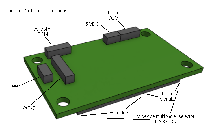
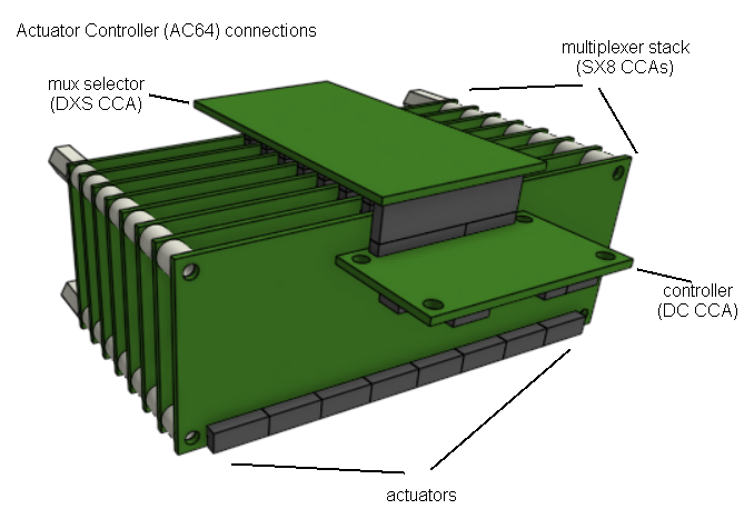
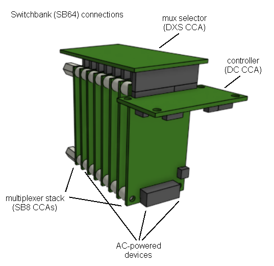
Aeon's Actuator Controller and Switchbank are both based on the same "Device Controller" printed circuit board, programmed with different microcontroller firmware. Additionally, a few components that monitor actuator voltage and current are omitted from the Switchbank. Otherwise, the two circuit card assemblies are physically identical. The long header with the address bus and device signals plugs into a Device Multiplexer Selector (DXS CCA), which serves as a sort of "motherboard" or "backplane" for the Actuator Controller and Switchbank assemblies.
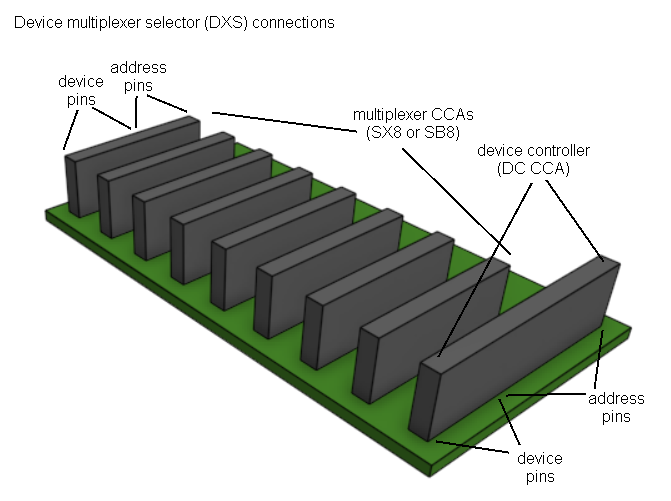
A stack of one to eight eight-channel multiplexer cards is also plugged into the DXS, providing as many as 64 channels per assembly. In the case of the Actuator Controller, the multiplexer stack comprises Servo Multiplexers (SX8 CCAs). The Switchbank stack is made up of SB8 Switchbank Multiplexer circuit card assemblies.
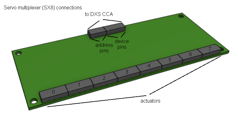
Each servo multiplexer has a row of 40 pins along one edge. These comprise eight groups of 5 pins each, one group for each actuator that may be plugged into the multiplexer. Care is required when plugging devices into the multiplexer, because there are no keys or other physical mechanisms to ensure the connectors are plugged onto the correct pins. It is possible to plug a connector in backwards, or onto some pins of an adjacent channel. Generally, such errors will damage neither the actuator nor multiplexer, but they will prevent the devices from working properly.
The Actuator Controller accommodates two kinds of actuators: those controlled by command pulse-width (CPW actuators), and those managed via serial communications (RS232 actuators).
CPW actuators have three conductors, usually colored brown-red-orange. Brown is GND and always goes to pin 1. The cable connector mates to the first three of the five pins for the selected channel on the multiplexer; pins 4 and 5 are left empty.
RS232 actuators require four conductors: brown, red, orange, and yellow. The four wires are inserted into a five-pin connector housing, with the slot for pin 3 left empty. Brown and red go to pins 1 and 2, respectively, and orange and yellow go to pins 4 and 5. Thus, when this connector is mated to the selected multiplexer channel, there is no connection at pin 3.
Either type of actuator may be plugged into any available channel, so select channels to avoid tangles. Don't forget to include a reasonable service loop at each end of the cable, so it will not be stretched to reach its destination.
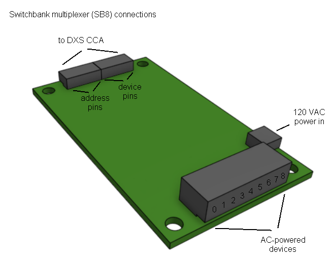
A Switchbank multiplexer (SB8 CCA) has a sixteen pin header on one end, arranged eight pins by two. Each of the eight pairs can provide up to 1 amp of 120 VAC power to a single device, such as a fan or solenoid valve. When wiring a device to the multiplexer, the neutral wire always goes to the pin nearer to the multiplexer printed circuit board.
Devices controlled by the Switchbank should be wired with violet+gray two-conductor ribbon cables, or spliced to such a cable, if the device is provided with flying leads instead of terminals. The gray wire is to be used for Neutral and must go to pin 1 of the cable connector.
In general, route the cables to the Switchbank according to convenience, in as few bundles as is practical. Prevent contact with components that may get hot, and especially at bends, ensure the cables do not contact sharp, unprotected metal edges. Do not bundle (zip-tie) these cables together with other types of cables (i.e., non-AC power cables). Additionally, make a particularly concerted effort to avoid any close proximity to sensor cables, including those for thermocouples, pressure gauges, and silicon temperature sensors. Where perfect avoidance is impossible, keep the gap between the two cable types as wide as possible, and the length of their adjacency as short as possible.
AC-powered devices may be connected to any available Switchbank channel, so select channels to avoid tangles. Don't forget to include a reasonable service loop at each end of the cable, so it will not be stretched to reach its destination.