

Aeon Laboratories LLC
5835 N Genematas Dr
Tucson, AZ 85704
1-520-690-0012
www.aeonlaboratories.com
Aeon Laboratories LLC
5835 N Genematas Dr
Tucson, AZ 85704
1-520-690-0012
www.aeonlaboratories.com
"Aeon" is Aeon Laboratories, LLC, Tucson, AZ, USA.
Manufacturer Address
For ordering information, sales support, or technical assistance, visit Contact Us on www.aeonlaboratories.com.
This manual is provided "as is." Its contents are subject to change without notice.
Aeon makes no representation that this documentation is complete, accurate, or error-free. Aeon assumes no responsibility nor liability for errors, omissions, damage or loss that might result from the use of this document, even if all instructions in the document are followed properly.
This manual provides general installation, operation and maintenance instructions for Aeon Carbon Extraction and Graphitization Systems (CEGS). Before installing or operating your CEGS, read this manual carefully. Become familiar with both the manual and your system. The manual contains important information about operator safety and the proper use of the system.
Important safety information is presented in this manual as follows:
 A Caution indicates that failing to follow an instruction could result in damage to equipment or failure of the process.
 A Warning indicates that failing to follow an instruction could result in injury or death to people.
Warning -- read documentation for hazard detail.
A Warning indicates that failing to follow an instruction could result in injury or death to people.
Warning -- read documentation for hazard detail.
 Warning - electric shock.
 Warning - extremely low temperatures.
 Warning - hot surface.
The CEGS is an automated process control system, intended for extracting carbon from various types of samples, and converting the extracted carbon into a form suitable for radiocarbon (14C) analysis by accelerator mass spectrometery (AMS). The CEGS is intended for operation only by qualified personnel in a laboratory environment.
The correctness and safety of the system software and configuration is the responsibility of the user.
In order to enable unrestricted sample processing research, the fully open-source system software is easily modified by the user. This flexibility gives the user complete control over every aspect of the instrument. Make frequent backups, and exercise extreme care when making software and system configuration changes.
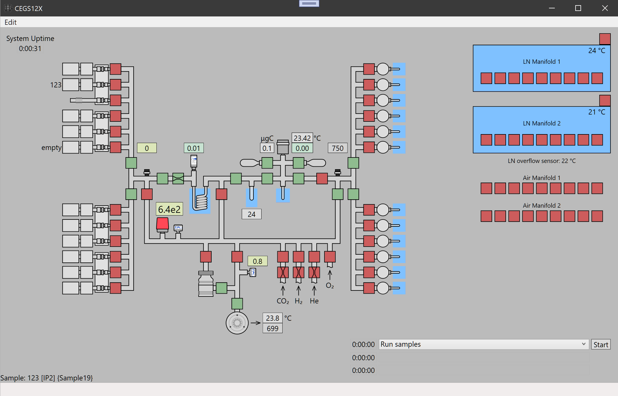
A typical CEGS user interface.
Hovering the mouse over any element displays its description in the status bar at the bottom of the window. Additionally, tool-tip with detailed configuration and state data will pop up for most items. An item-specific context menu is raised when a controllable item right-clicked.
In the main schematic diagram, the colored squares represent valves; red are closed and green are opened. Metering valves are illustrated with a restriction inside; these enable precise flow control. System chambers are formed by tubes and fittings (plumbing) between the valves. Most pressure sensors are illustrated and have numeric displays. Some thermometers are displayed numerically, as well. Other simple rectangles and circles represent heaters or other devices, such as fans. Most light up with an indicating color when in operation.
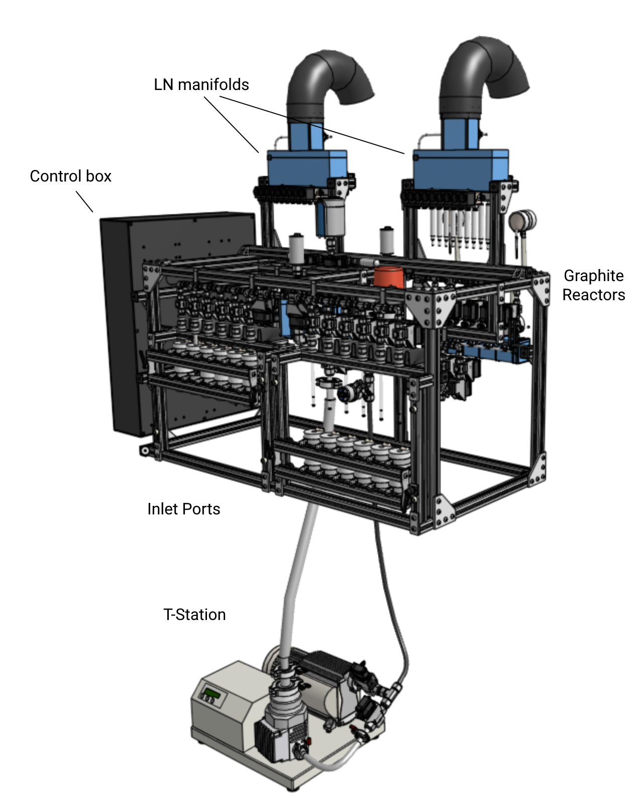
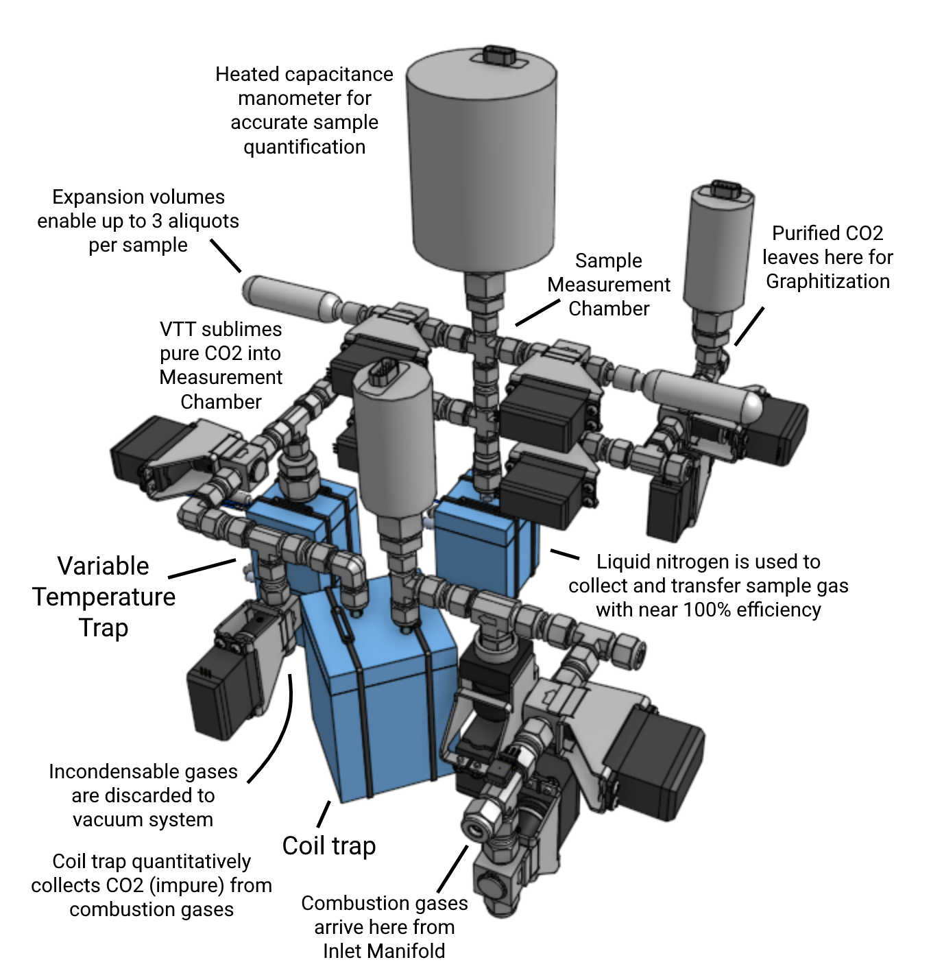
An array of inlet ports (IPs) connect to the inlet manifold (IM) at the left. The graphite reactors (GRs) are on the graphite manifold (GM) at the right end of the plumbing. The core process section is shown between, comprising a coil trap (CT), a variable-temperature trap (VTT), the measurement chamber (MC), and a small split chamber used for sample-sizing (Split).
Below the process section, the vacuum section includes the vacuum manifold (VM), gas supplies, and the vacuum system. The vacuum system usually operates as an autonomous unit. That is, the user clicks "Evacuate" or "Isolate", rather than directly controlling the vacuum system valves.
Floating at the far right are the liquid nitrogen (LN) and compressed air manifolds. These distribute LN and air to coldfingers (FTCs and the VTC), shown in blue on the main diagram.
At the bottom right is a drop-down list of pre-defined processes which may be selected and started. When a sample is selected or "in process", its data appears at the bottom left.
Many of these performance metrics are profoundly influenced by laboratory conditions and practices, over which Aeon has no control. Others are dependent on the specific system configuration. Therefore, they cannot be guaranteed, and Aeon reserves the right to adjust them at any time without notice. However, the numbers presented here are based on actual factory tests and typical past performance of very similar instruments manufactured by Aeon. As such, they do offer a true and fair representation of the performance capabilities of Aeon's CEGS, and can confidently be used to make meaningful comparisons to alternative approaches.
The person or persons installing the CEGS are responsible for ensuring the safety of the system, themselves, persons nearby, and subsequent users.
The electrical connection of the CEGS to facility power must be made by qualified personnel in accordance with all applicable regulations.
Only trained, qualified personnel may make the gas supply connections to the CEGS.
Only trained, qualified personnel may make the liquid nitrogen and compressed air supply connections to the CEGS.
All personnel participating in the installation and operation of the CEGS must have a full understanding of the hazards presented by the instrument and the substances (gases, liquids) involved. All installation personnel must observe any precautions identified on the material safety data sheets (MSDS).
Voltages up to 120 VAC are present inside the CEGS control box. Do not work on anything inside the control box unless the power cable is unplugged.
Voltages up to 120 VAC are present in some of the cable harnesses attached to the CEGS frame. 120 VAC conductors are always protected with violet (Line) and gray (Neutral) insulation, and their terminals are also fully insulated. Nevertheless, do not touch these wires or their terminals unless the control box power cable is unplugged.
The CEGS requires independent, external gas detection and monitoring.
The facility where the CEGS is installed must be equipped with a gas detection system to monitor the ambient concentrations of oxygen and hydrogen in the laboratory. The gas detection system must meet the following requirements:
The gas detection and shutoff systems must be installed, maintained, and regularly tested by the facility to ensure their continued functionality and compliance with safety standards. It is the responsibility of the facility to establish these measures before the equipment is commissioned.
The CEGS requires a sturdy work surface.
The system is designed to rest on a sturdy work surface, such as a laboratory table or bench top, accessible from at least three sides. The bottom of the CEGS frame fits within a rectangle 1050 mm wide x 520 mm deep. The work surface should be capable of supporting at least 75 kg. The work surface height should ensure convenient access to the inlet ports and graphite reactors by a standing user; typically 760 to 1050 mm is acceptable.
Additional space, typically on a shelf or the floor below the work surface, is required for the Vacuum Pump System vacuum pumps (395 x 350 mm) and the UPS (150 x 395 mm).
Provide sufficient free space near the liquid nitrogen manifolds for a liquid nitrogen supply cylinder.
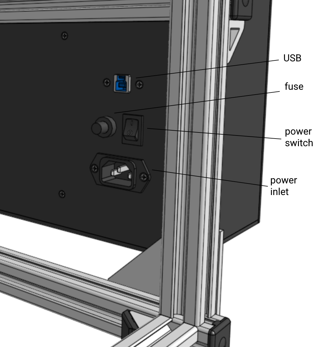
Make sure the Control box power switch can be reached at any time.
See Technical Data, Mains power
The CEGS requires liquid nitrogen. A standard liquid nitrogen cylinder with a 140-240 kPa (22-35 psi) pressure relief valve is suitable. Typical liquid nitrogen consumption per sample is usually less than three liters but can reach up to six liters on systems with multiple liquid nitrogen (LN) manifolds. This variation is largely due to "flash-off"—the immediate vaporization of nitrogen as it cools the receiving vessel during transfer. Systems with multiple manifolds often experience higher consumption due to increased surface area and transfer activity, which amplify flash-off losses.
The CEGS requires compressed air: 170 kPa, 140 L/min (> 25 psi, 5 CFM)
The CEGS may require some or all of the following gases to be provided from dedicated pressure-regulated cylinders.
The maximum pressure at any compressed gas inlet on the CEGS must be limited to no more than 30 psi at the source. The maximum required process pressure for any CEGS gas supply is 15 psi. Aeon recommends that all gas supply lines be protected by a suitable pressure limiting safety device.
See Technical data, Operating conditions.
Provision should be made to collect or redirect the condensation that will drip from the various elements of the liquid nitrogen distribution system. The majority of this moisture is generally concentrated in the vicinity of the LN supply cylinder connection.
Inspect the shipping container for signs of damage, and after unpacking, inspect the CEGS for any indication of mechanical damage that may have occurred in transit. If you suspect the machine was damaged in transit, immediately notify the carrier and Aeon about the damage.
The CEGS is unpacked by disassembling the crate from around it. Begin by removing the crate top. Then detach and remove any accessory containers that may be attached to the hold-down bars. Next remove the bars that secure the CEGS vertically in the crate, and remove the crate sides. Remove the plastic cover from the CEGS. Then, remove any containers or sub-assemblies that are strapped onto to the base plate with the CEGS. Finally, unstrap the CEGS from the base plate.
 Heavy, bulky load.
The CEGS is too big and heavy to be handled by one person. At least two people, and preferably more, are needed to lift it from the crate onto the work surface. Do not lift the instrument by the Control box. Lift by the frame.
Once the CEGS is in place, remove the straps from the control box. Remove the control box cover, inspect for loose items, then replace the control box cover.
Carefully remove the zip ties and packing materials that support and secure the inlet port furnace carriages and the graphite reactor furnaces.
Remove the bundle of plastic tubing that is fastened to the CEGS.
Unstrap the wrapped blue foam parts from the CEGS frame and unwrap the devices inside.
Remove the temporary plugs and caps from vacuum system openings. Remove the wire-ties securing loose pressure sensor connectors.
Open each inner container, and unwrap and identify the contents.
Install the Vacuum Pump System valve assembly on the Vacuum Pump System.
Install the measurement chamber (MC) coldfinger and MC FTC.
Install the coil trap with the CT FTC.
Install the VTT coldfinger and the VTC.
Install the FTC air tubes.
Install the LN manifolds:
Install the phase separators:
Install the FTC LN tubes.
Install the pressure sensors
Follow this procedure to prepare the CEGS for use at a new location.
Place the UPS beneath the CEGS works surface, near the CEGS control box.
If there is a mains power converter, place it beside the UPS.
Place the Vacuum Pump System beneath the CEGS work surface, so the Vacuum Pump System control panel is readily accessible, and the HV and foreline tubes can be routed to their connection points in the CEGS. Ideally, the HV and Foreline tubes should pass through holes drilled in the work surface.
Connect the HV and foreline tubes between the Vacuum Pump System and the CEGS.
Route the vRvB cable harness along the foreline tube and connect it to the CEGS.
Place the CEGS laptop host computer in a convenient location near the CEGS. The laptop charger power cable must reach the UPS.
If there is a mains power converter, plug the UPS into the converter outlet labeled "CEGS UPS". Otherwise, plug the UPS into a facility 120 VAC outlet.
Plug the following items into Battery + Surge outlets on the UPS:
Plug the CEGS mains detect power cube into a Surge outlet on the UPS (not into a Battery + Surge outlet); plug the mains detect cable into the power cube.
Plug the USB 3.0 SuperSpeed cable into the USB connector of the control box. (Leave the other end disconnected from the laptop for now.
Locate the LN cylinder behind the left or right end of the CEGS. Select the position to ease the routing of the LN supply tubes to the phase separators.
Connect the LN supply plumbing to the LN cylinder.
Route the LN supply tubes to the phase separators. Note: An LN flow restrictor is inserted into the compression fitting at the solenoid valve, before tightening the compression fitting nut.
If necessary, remove the sleeve from the supply line, and use a heat gun to re-form the tube to reach the phase separator.
Position the LN Overflow sensor on the work surface beneath the LN manifold, and secure it in place with tape.
Place a Yeti cup or other suitable LN container on the work surface under the VTC drain.
Connect the facility air supply line to the CEGS.
Ensure the interiors of the sample and graphite reactor furnaces are free of dust and other foreign material by blowing a moderate stream of compressed air or nitrogen into the bottoms of the furnaces. Use a nozzle long enough to reach the bottom of the furnace well.
Connect the gas supply tubes to the CEGS.
Power up the system according to the CEGS Startup sequence.
Evacuate the gas lines before setting pressures. When adjusting the gas pressures, make sure enough gas is moved to purge the supply lines of air and residual moisture. Set the gas cylinder pressure regulators, using pIM or pGM to check pressure:
The complete system configuration and all state data are stored in the CEGS installation folder, in a single file named "settings.json". When the CEGS is running, the settings file is updated twice per second. The file may be modified using any text editor; however, the CEGS application must be closed while the file is edited; otherwise, the system will overwrite your changes.
While the CEGS is running, messages about errors and other important events that require operator attention are transmitted by an alert manager. These messages are sent to the system's own private email account. System operators can configure a remote device, such as a cell phone, tablet, or other computer to receive these messages.
To receive system alerts, you must obtain the system email address and password. These are accessible from within the CEGS application, under Edit > Settings, then AlertManagers > CEGS AlertManager > SmtpInfo. The fields Username and Password contain the system email address and password, respectively. Use these values to set up a new email account on the alert device:
Basic information
Example: Android device, using Samsung Email app
Example: iPhone
The CEGS is operated from a computer configured specifically for the instrument. The provided software is based on Aeon's Hardware Automation Control System (HACS). HACS is a fully open source (GPL3) software framework designed to enable a programmer to quickly create a Windows application to control a machine or instrument. HACS and the instrument-specific CEGS source code are written in C#, using Microsoft's Visual Studio.
The user can individually control most system elements via the graphical user interface, which resembles a schematic diagram. For example, they could close or open a valve, or adjust the digital filter for a pressure sensor. See User Interface for a brief introduction to the user interface.
However, the user can also select a named process from a drop-down list, and click Start to begin the process. A process is typically a relatively limited task, such as "Admit H2 into the selected graphite reactor", or "Flush the inlet port three times with helium", or "Measure the purified CO2".
Finally, with the Process Sequence Editor, the user can string together a series of processes into a "Process Sequence" which fully processes a sample. For example, the default "Organic" process sequence combusts a sample, collects the gas products, isolates and purifies the CO2, measures the CO2, and then graphitizes it (i.e., using hydrogen to reduce the CO2 gas to solid carbon on an iron catalyst.)
Results are stored in a Sample data text file, and optionally in a user-defined text file for importing into another program.
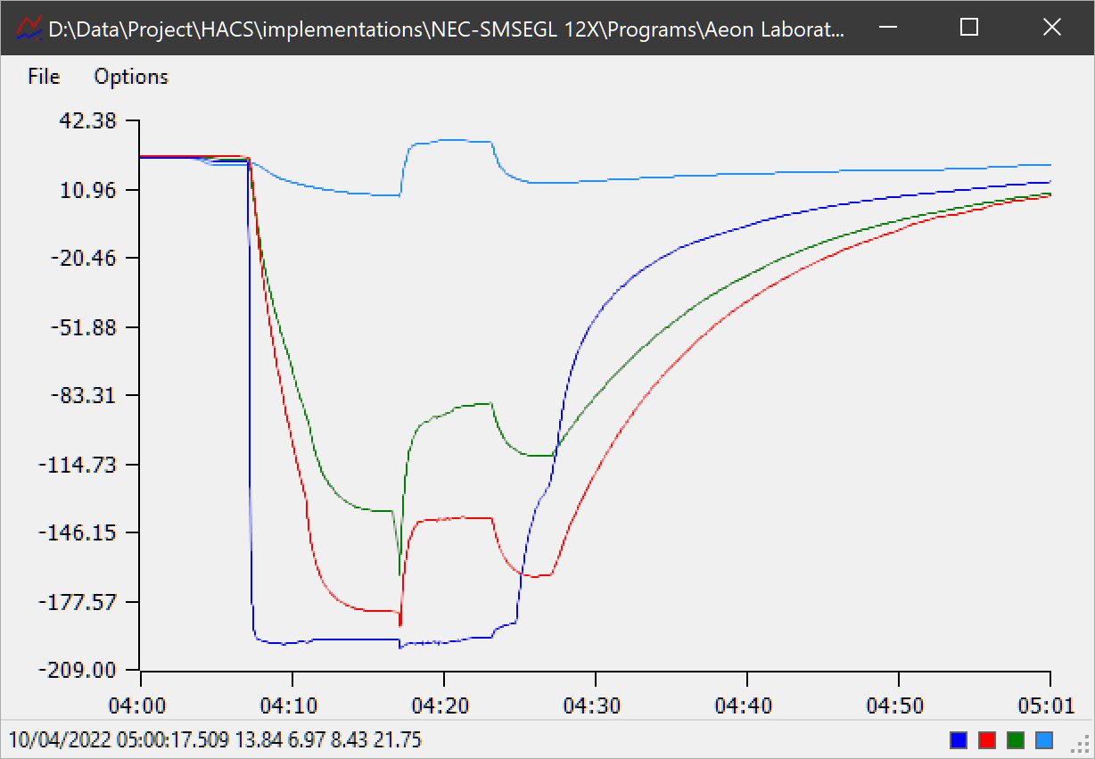
Additionally, the CEGS continuously monitors temperatures and pressures throughout the system, and records them in a series of log files, which are archived daily. Aeon's Data Visualizer application can present these data in graph form live, or anytime (even years) later.
Follow this procedure to power up the system.
Follow this procedure to power down the system.
If the plug valves are left in the same position for an extended time (more than a week or so), they become increasingly difficult to turn. This happens because the continuous vacuum slowly squeezes the O-ring grease out from between the O-rings and cylinder wall in the plug valve body. To restore normal operation, exercise the plug valves (close and open) several times, to re-lubricate the O-rings.
To start a process, select the desired process from the drop-down list at the bottom right of the user interface, and then click Start. The Start button is hidden while a process is running.
Even when a process is underway, the operator can directly control the system elements via the user interface. This can be useful in many circumstances. However, this capability also makes it possible for the user to disrupt automatic operations, and can cause the loss of a sample. Therefore, Aeon recommends avoiding manual control of the system while automatic process control is in progress.
To abort a process, close the CEGS application by clicking the [X] in the upper right corner of its window. Then restart the application. The system state is preserved, but the process is terminated.
After aborting a process, it may be necessary to alter the state of various system devices. For example, a heater may need to be turned off, or a coldfinger might need to be thawed, etc. Typically, these are operations that would have been done by the system, had the process continued normally. In such cases, the operation is usually performed by right-clicking on the device in the user interface to bring up the device's context menu, and then selecting the desired operation from the list presented.
Whenever the CEGS application is running, pressure and temperature data are continuously recorded into several system log files. By default, these logs are located in a folder named "log" which resides in the application folder. Each day, most of the log files are archived to a folder named "archive" under the log folder. Aeon's Data Visualizer utility can display the log data in a graph. To view a specific log, open the Data Visualizer, and drag and drop the log file onto the Data Visualizer window. Alternatively, you can use the File > Open menu item and navigate to the desired file to open it.
Aeon recommends compressing old log files into a ".7z" or ".zip" archive on an annual basis. It is also wise to maintain a daily backup of the log folder tree on an independent device or cloud service.
By default, two logs are not archived automatically on a daily basis. These are the system "Event log.txt" and the "Sample data.txt". These files should be archived manually on a regular basis, or when they become excessively large.
The usual course of action to process samples through the CEGS consists of three steps: 1. Prepare the graphite reactors, 2. Load the inlet ports, and 3. "Run" the samples.
It is most efficient to combine the unloading of the previously graphitized samples and the loading the new reactor tubes into a single task.
Each graphite reactor accepts two 6 mm borosilicate culture tubes. The vertical tube contains a desiccant, usually anydrous magnesium perchlorate. For brevity, we call this tube "the perchlorate tube". The horizontal tube contains a small amount of powdered metal catalyst, usually iron. For brevity, we call this tube "the Fe tube", as iron is the most common and usually preferred catalyst. When the graphite reaction is complete, the iron powder will be covered, more or less, with the black carbon test sample destined for AMS, but we will still refer to the tube as the Fe tube.
Never touch culture tubes with gloved hands.
Throughout all procedures, when preparing the tubes, and when loading and unloading the graphite reactors, never touch the Fe or perchlorate tubes with gloved hands. This would impart a static charge to the glass, which can easily attract contaminant dust and spoil the sample. You can safely handle the Fe and perchlorate tubes with bare hands. However do not touch within 1 cm of the open ends of the tubes. Any skin oils left there would compromise the O-ring seal in the graphite reactor and could cause the loss of the sample.
Furnaces may be hot.
Raise the graphite reactor furnaces. Do not touch the furnaces or any metal parts on them. Raise and lower the furnaces with the silicone rubber covering on the GR furnace arm. Wait, if needed, for the graphite reactor glass to cool before continuing.
In the CEGS application, start the process "Prepare GRs for new iron and desiccant". When prompted, mark the Fe tubes to clearly identify their contents. Press Ok to continue. After the system back-fills the reactors with inert gas, a message will prompt the operator to replace the Fe and perchlorate tubes.
First, remove the old Fe tubes and cover them with foil caps. Move them as soon as possible to a dust-free area, such as a laminar flow bench, for packing into AMS targets. Then remove the old perchlorate tubes. A gentle tap on the work surface will loosen the spent perchlorate, so that it may be dumped into an intermediate container for subsequent disposal in accordance with regulations.
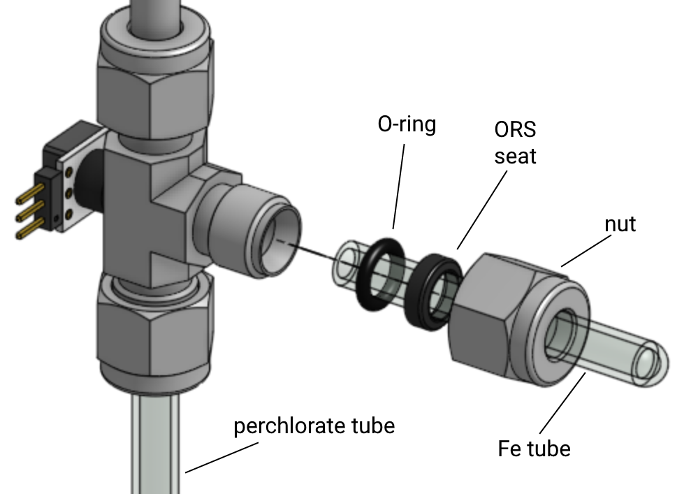
Into each graphite reactor, install fresh Fe and perchlorate tubes, replacing their O-rings at the same time.
Be sure to re-assemble the graphite reactor correctly.
Take care to avoid misplacing the O-ring seal seat, the circular plastic ring that compresses the O-ring into the graphite reactor fitting. If the seat comes out of the nut, make sure to orient it correctly when returning it to position. The conical face of the seat goes toward the fitting, and the O-ring goes between the seat and the fitting.
In the CEGS application, start the process "Precondition GR iron".
CEGS inlet ports accept 9 mm or 3/8" diameter tubes.
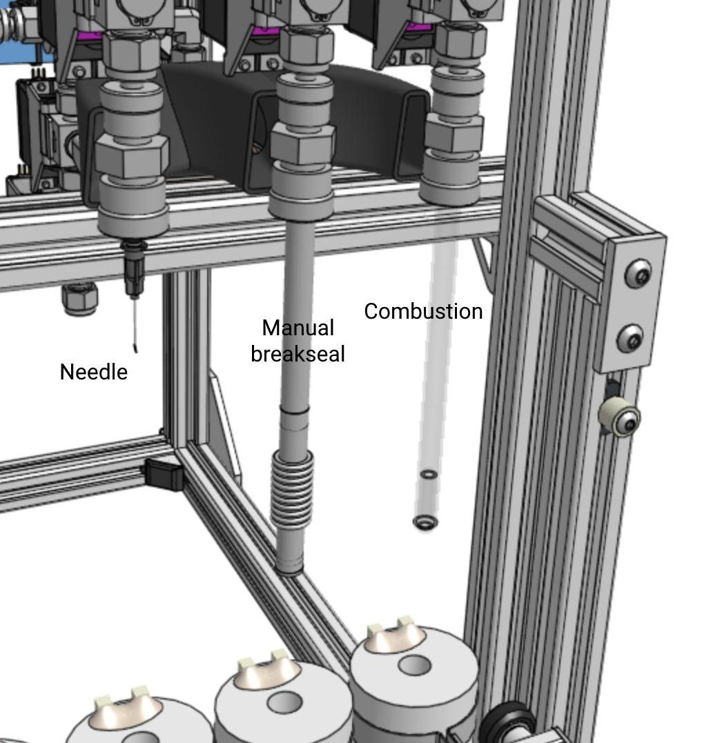
Organic and other samples that will be combusted to liberate their CO2 are loaded into 9 x 150 mm quartz combustion tubes for processing by the CEGS. The system refers to this inlet port configuration as type "Combustion".
Samples that will be subjected to a wet chemistry procedure to liberate their CO2 can be conveniently processed in septum-sealed vials. To accommodate these, a 3/8" tube to Luer adapter is provided with each inlet port, along with a needle and a silicone stopper. Aeon recommends processing carbonate samples in septum sealed vials for extraction and graphitization by the CEGS. The system refers to this inlet port configuration as type "Needle."
A breakseal adapter, suitable for 6 mm x 125 mm sealed glass ampules, is provided for processing sealed CO2 gas samples. At the appropriate time, the system notifies the operator to release the sample, by bending the adapter, which breaks the ampule. Because operator intervention is required to release the sample, the system refers to this inlet port configuration as type "Manual."
It is important to load the combustion tube as follows:
 Never touch quartz combustion tubes with gloved hands.
Throughout all procedures, never touch the combustion tube with gloved hands. This would impart a static charge to the glass, which can easily attract contaminant dust and spoil the sample. You can handle the tube with tweezers, with a strip of foil, or even with bare hands if careful. If using bare hands, do not touch the combustion tube within 1 cm of the rim. Any skin oils left there would compromise the O-ring seal at the inlet port and could lead to a lost sample.
Handle quartz durham tubes with clean tweezers only. Never touch with hands.
The durham tubes go into the combustion tube with the sample. Any contaminants on the durham tube will be mixed into the sample CO2 and compromise the sample.
A combustion chamber loading template is provided with the system.
To load the combustion tube into the inlet port, first lower the furnace carriage. Then loosen the nut at the bottom of the port, insert the combustion tube and back it off about 1 mm away from the shoulder inside the port, then tighten the fitting nut.
Needle ports are used to process CO2 gas, commonly prepared by acid digestion of carbonate samples. First, lower the furnace carriage. Then insert the needle port adapter, with the needle and stopper attached, into the inlet port and secure it by tighting the fitting nut. The vial must be evacuated before acid digestion. The process "Prepare carbonate sample for acid" does this. Additionally, after digestion, the vial must be loaded onto the needle, while avoiding atmospheric contamination. This is accomplished by running the process, "Load acidified carbonate sample". In both of these processes, it is important to follow the on-screen instructions carefully.
Manual ports are used to process CO2 gas in sealed glass ampules. Before loading the ampule into the breakseal, carefully clean the ampule, score it approximately 25 mm from one end, and gently insert it scored end first into the breakseal. Lower the furnace carriage. Then insert the breakseal into the inlet port and tighten the nut. At the appropriate time, the system notifies the operator to release the sample, by bending the adapter, which breaks the ampule.
After the samples have been loaded into inlet ports, use the Sample Editor (Edit > Samples, then New...) to enter the sample information into the CEGS.
To select and run the loaded samples, Start the "Run Samples" process. A sample selection dialog appears with a list of available samples. Select which samples to run, confirm and check-off the conditions in the checklist, and then click Ok to begin the first sample. The system sends a notification when the samples are complete.
Aeon recommends replacing inlet port O-rings and frits periodically or whenever visible contamination is detected in the inlet port cold trap. This area should be inspected every few weeks, or immediately after any large, dirty sample, such as bulk sediment, has been processed. To inspect the cold trap, remove the nut, ferrule, and O-ring from the bottom of the trap. Moisten a clean cotton swab with isopropyl alcohol and wipe it in a circular motion inside the fitting. If any discoloration appears on the swab, the port needs service. After service, or if none is needed, re-assemble the cold trap for continued use.
To service the port, remove the cold trap (Ultra-Torr fitting) from the tube that enters the inlet port valve. Completely disassemble the cold trap. Thoroughly clean its interior and ferrules with isopropyl alcohol. A a nonwoven abrasive pad may be necessary to remove stubborn deposits. Install a new frit and new, baked-out FKM O-rings. Avoid touching O-rings with your hands (use tweezers) and use absolutely no grease.
Before re-installing a serviced cold trap, moisten a clean cotton swab with isopropyl alcohol and wipe it in a circular motion inside the tube that enters the inlet port valve. If any discoloration appears on the swab, the inlet port tube requires service. After servicing the inlet port tube, or if service is not required, re-install the cold trap for continued use.
Make a mark on the front of the nut that secures the inlet port tube to the inlet port valve; then loosen the nut from the inlet port valve using a 9/16" wrench, taking care to hold the valve body stationary with an adjustable wrench to avoid torquing the inlet manifold above. Remove the nut and tube from the valve. Remove the inlet port screen from within the valve inlet fitting, clean the fitting inlet with cotton swabs and isopropyl alcohol, and replace the inlet port screen with a new one. Do not attempt to clean and reuse a dirty inlet port screen.
Thoroughly clean the interior of the inlet port tube using only isopropyl alcohol and cotton swabs. The interior of the tube is electropolished to a mirror finish. If the tube is not easily restored to its "like new" mirror finish condition, contact Aeon for a replacement. Additionally, if there is any reason to suspect that the inlet port valve may be contaminated beyond the inlet port screen, contact Aeon for guidance; major maintenance may be required.
Do not reinstall the inlet port tube without a new inlet port screen.
The inlet port screen provides critical protection to the inlet port valve, the inlet manifold and the vacuum system. If you must operate the CEGS with an inlet port screen absent (for example, while a new one is on order), then disable the port from its context menu in the CEGS application, and do not use that port or open its valve until the screen has been replaced.
After cleaning the inlet port tube and replacing the inlet port screen, reassemble the inlet port tube into the inlet port valve. Re-tighten the fitting nut only enough to restore the mark to its original position.
Aeon recommends replacing both the iron and perchlorate port O-rings between samples. Use only FKM O-rings, preferably baked-out, and never grease.
Service every two years, more often with heavy usage, or if valve performance is degraded.
Maintain vacuum system pumps in accordance with the manufacturer recommendations. Refer to the individual pump manuals for details.
Perform the shutdown procedure.
Follow this procedure to prepare the CEGS for moving to a new location.
Throughout the term of storage, ensure that the proper storage conditions are maintained.
Dispose of system in accordance with all applicable safety and environmental regulations. Do not incinerate.
Consumable materials used in the CEGS may be purchased from Aeon, but it may be more economical to purchase readily available items from the OEM or larger distributors.
Spare and replacement parts for the CEGS can be found at www.aeonlaboratories.com/?page=search. If you can't find what you are looking for, please Contact Aeon for assistance.
Do not allow higher than the recommended pressure. Hold culture tube securely. Blow off the outside top of culture tube first. Then insert nozzle down to bottom of tube. Squeeze and hold trigger while withdrawing the nozzle up and out of the culture tube. Failure to follow these instructions carefully can launch a culture tube with dangerous velocity.
Wipe the probe tip with a lab wipe before first use of the session, then blow clean dry air or nitrogen across it to ensure no dust or lint remains on the probe tip. Roll the Fe powder vial between fingers at an angle to loosen the powder and shift it toward the vial opening. Collect a small amount of powder on the probe tip by dipping into the powder. Carefully withdraw the probe from the vial and hold it above the weighing paper in the balance. Gently tap the probe handle to release some powder onto the paper. Close the balance door and wait for the reading to stabilize. If the mass is too low, add more Fe by tapping the probe as before. If it is too high, pick up some of the powder by gently touching the probe tip to the powder on the paper.
This tool is nothing more than a bent dissecting needle, or teasing needle, which has been magnetized at the tip. Any such needle is suitable as long as its needle is magnetic. Aeon provides this tool only because many dissecting/teasing needles are not magnetic.
Stand the magnet assembly on a magnetic work surface near the analytical balance. The larger magnet at bottom of the rod should be stuck to the work surface. The smaller magnet should be stuck to the top of the rod. Make sure a clean, already-flushed 6 x 50 mm pyrex culture tube is ready and within reach.
Take the weighing paper with the already-weighed Fe powder and carefully place the center of the paper onto the top magnet. The powder should instantly be collected on top of the paper toward the magnet beneath. Hold the magnet rod stationary with one hand and use the other hand to drag one edge of the paper under the powder away from the rod, until the powder approaches the opposite edge of the paper. The powder should remain 5-10 mm away from that edge.
Continue holding the rod, and with the other hand now under the paper, curl the sides of paper up into a U-shape, with the powder at the bottom of the U. About half way up the sides of the U, above the powder, pinch the sides together between your thumb and fingertip, and lift the paper and powder together straight up off the magnet. All of the powder should remain collected in place on the paper. Do not let the powder fall toward the magnet or shift on the paper.
With the hand that was holding the magnet rod, take the culture tube and hold it with the top tilted toward the bottom of weighing paper / powder. Place the base of the U by the powder onto the rim of the tube. The edge of the paper should be within the mouth of the tube. Rotate the tube and paper together as a single unit, so the tube becomes vertical, and the powder falls from the paper into the mouth of the tube.
Holding the tube vertically, place the side of the tube about 10 mm below the rim against the top magnet. Draw the tube upward until it leaves the magnet. All the the iron powder should now be collected at the bottom of the culture tube. Cap the tube with foil and store it in a suitable rack until time to load the graphite reactors.
The larger magnet at bottom of the rod is intended merely to store the tool on a convenient magnetic surface near the graphite reactors.
After the graphite reactors have been loaded with new Fe tubes: Hold the rod vertically with the small magnet on top. Raise the magnet straight up from below each Fe tube until it contacts the lower surface of the tube beside the metal fitting. Slide the magnet away from the fitting along the underside of the tube. Upon reaching the end of the tube, draw the magnet straight down away from the tube. The powder should form a "flower" at the tip of the tube.
Prepare a clean, disposable work surface near the analytical balance, for example, by placing down a fresh 6 x 6 weighing paper. Onto the work surface, place a fresh 3 x 3 weighing paper, to catch and recover any spilled sample material.
Select two clean sample loading funnels. (Aeon recommends cleaning the funnels between uses.)
Place one funnel, cone side down (i.e., inverted), onto the center of your 3 x 3 paper. Using clean tweezers, take a clean, baked out durham tube from its container. Insert the tube vertically, open end up, into the the inverted funnel. Place the second funnel, cone side up, onto the top of the durham tube.
Take the weighing paper with the weighed test sample from the analytical balance and place it onto the work surface. Use flat-tipped tweezers to pick up the far edge of the paper and tuck it into the gently pinched thumb and forefinger of your free hand, poised over the sample. Then use the tweezers to pick up the near edge of the paper and tuck it into the same pinch. The paper should form a teardrop shape with the top edges between the thumb and forefinger of your dominant hand, and the sample cradled on the paper beneath the pinch, still in contact with the work surface.
Lift the paper carefully, and bring the bottom of the paper's free edge into the loading funnel. Keeping the paper's edge within the funnel, carefully rotate the paper to pour the sample into the funnel. If needed, gently tap the paper so that all of the sample leaves the paper and enters the funnel. Discard the paper. If needed, gently tap the side of the funnel with the tweezers so all of the material fall from the funnel walls into the durham tube.
Slightly lift the top funnel, enough that you can reach between the funnels with the tweezers and take hold the durham tube with them; then, lift the funnel the rest of the way off of the tube and set it aside. Lifting the top funnel without holding the durham tube down may cause the tube to come out of the bottom funnel and spill the sample.
Lay a clean, baked-out combustion tube on the work surface beside the inverted funnel. Use the tweezers to place the open end of the durham tube into the mouth of the combustion tube. With the combustion tube still laying on its side, use the tweezers to push the durham tube into the combustion tube. Once the closed end of the durham tube is inside the combustion tube, lift and tilt the open end of the combustion tube, so that the durham tube falls smoothly to the bottom of the combustion tube.
Refer to the Combustion port loading procedure for additional details on preparing the combustion chamber for loading into the CEGS.